August 12, 2009: This is what I likeAugust 10, 2009: There is hope: 3 pin SMPS's are there
 August 8, 2009: small video on Ycap-effect and a bit larger video of scoped effect
 previous revision
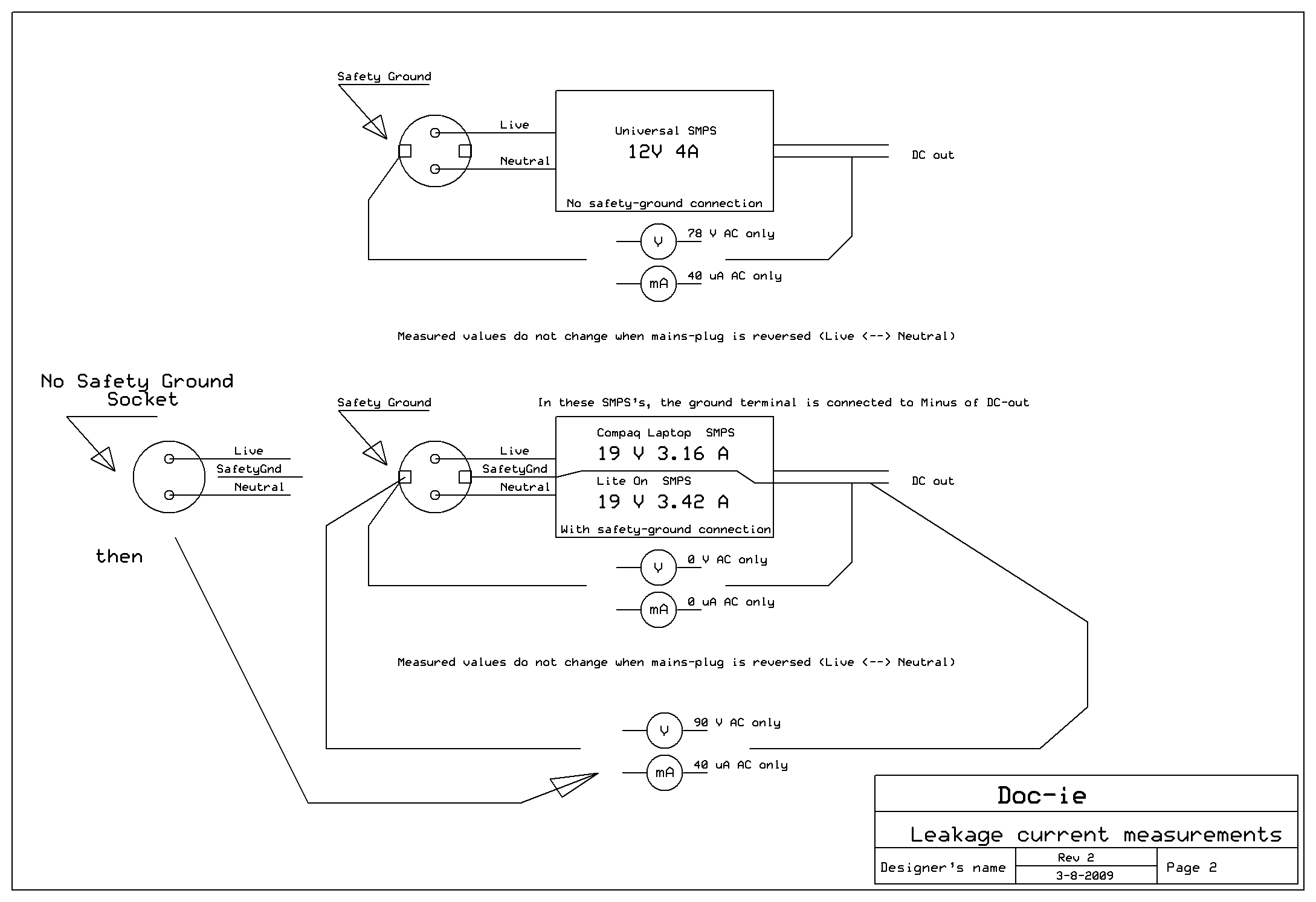
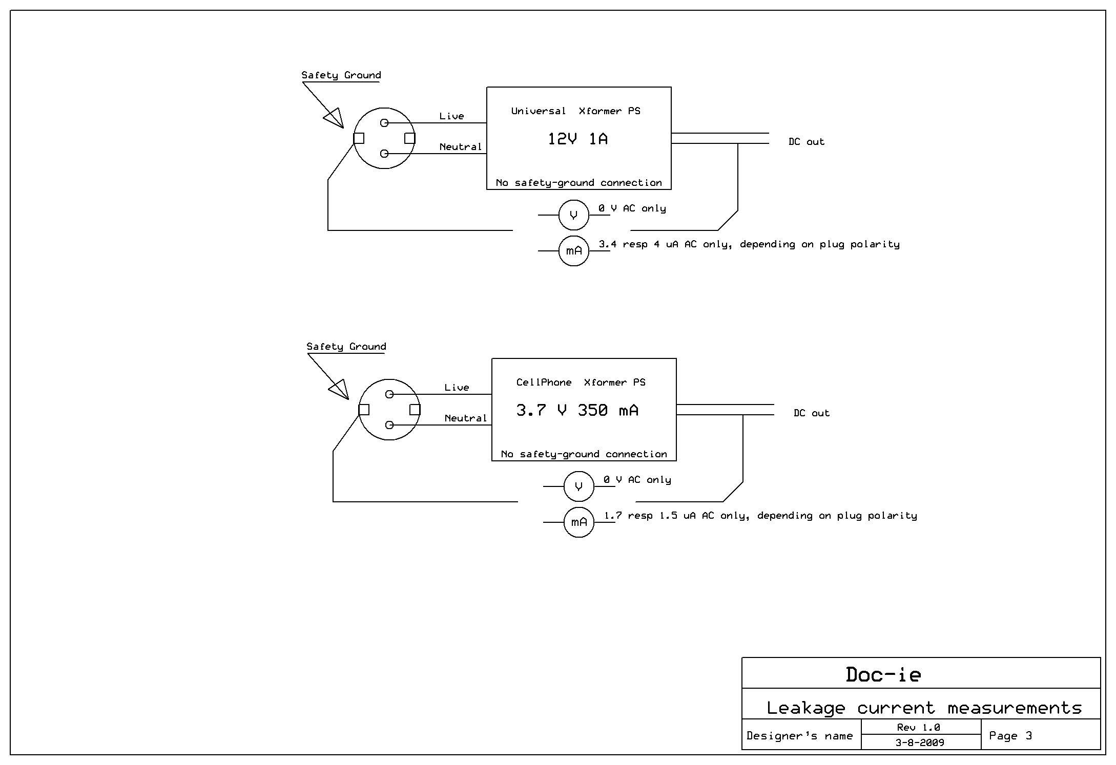
 a. Transformer based 5V 800mA stab wallwart for Ethernet hub |
 a. Transformer based 5V 800mA stab wallwart for Ethernet hub |
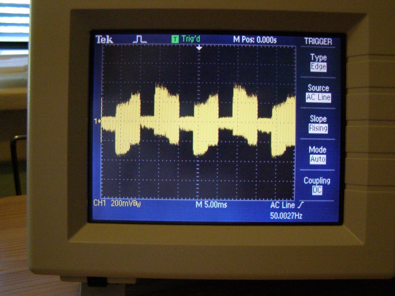
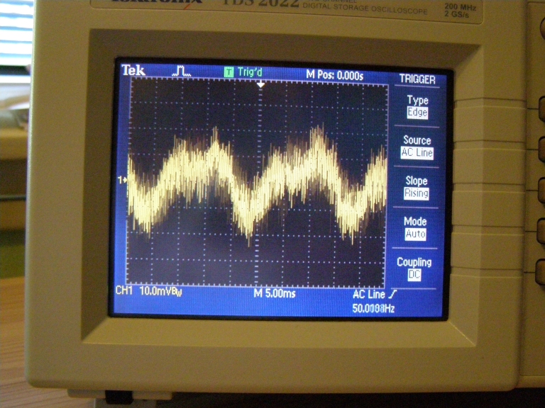
 a. Transformer based 5V 800mA stab wallwart for Ethernet hub: plugged in "one way" |
 a. Transformer based 5V 800mA stab wallwart for Ethernet hub: plugged in "the other way" |
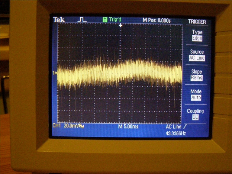
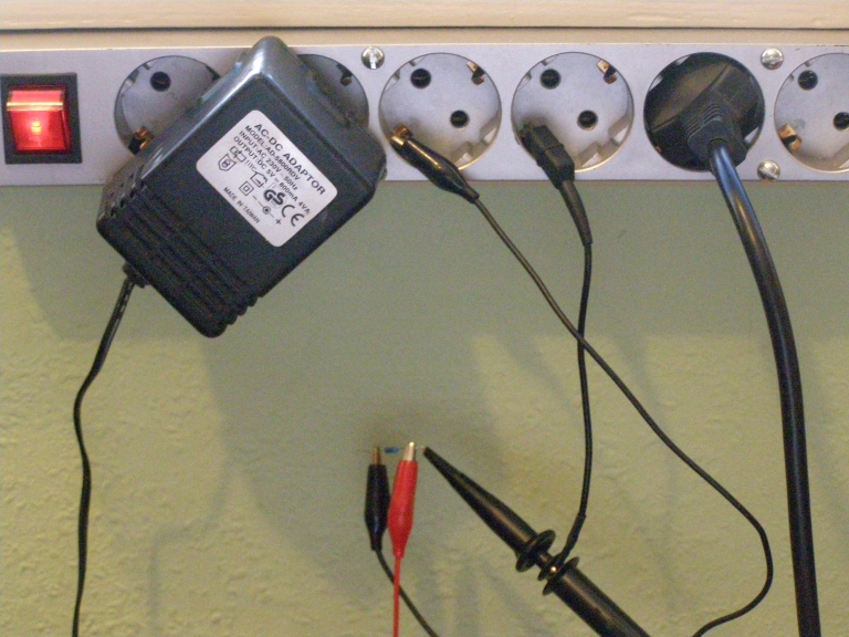
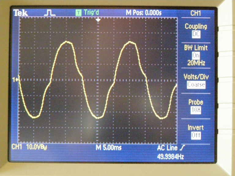
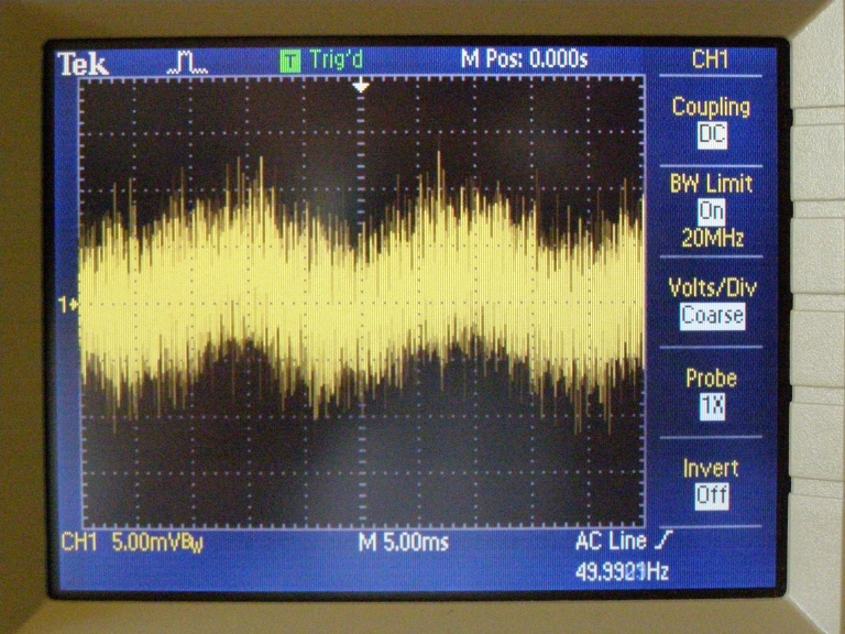
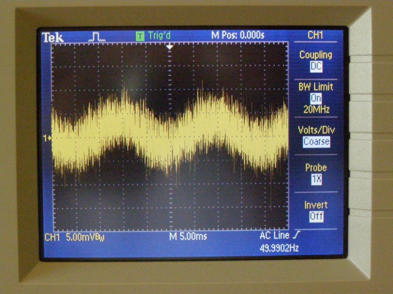
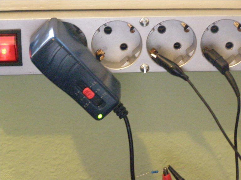
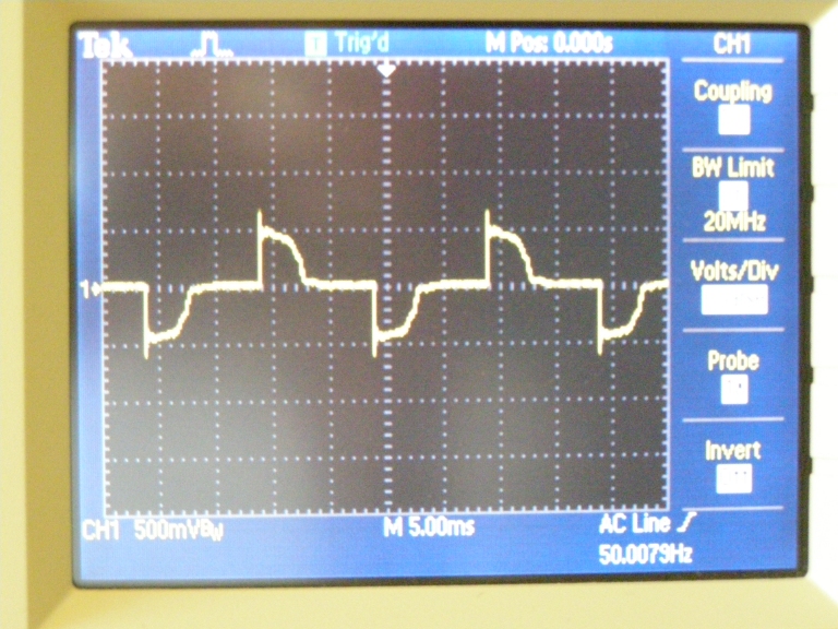
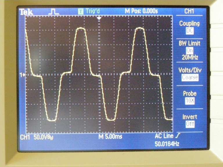
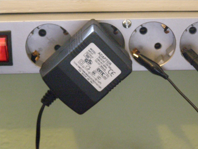 b. Transformer based 19V 500mA unstab wallwart for powerlights |
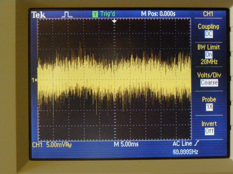 b. Transformer based 19V 500mA unstab wallwart for powerlights: current image over 1k |
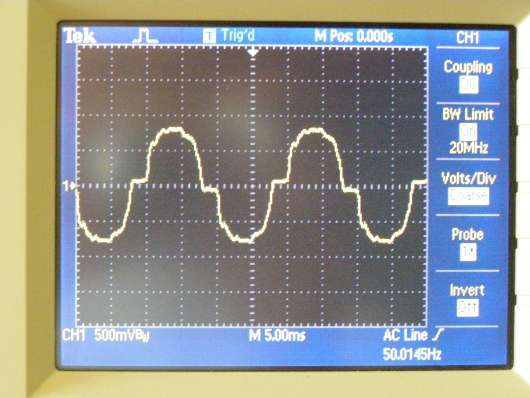 b. Probe 1x 1 MOhm |
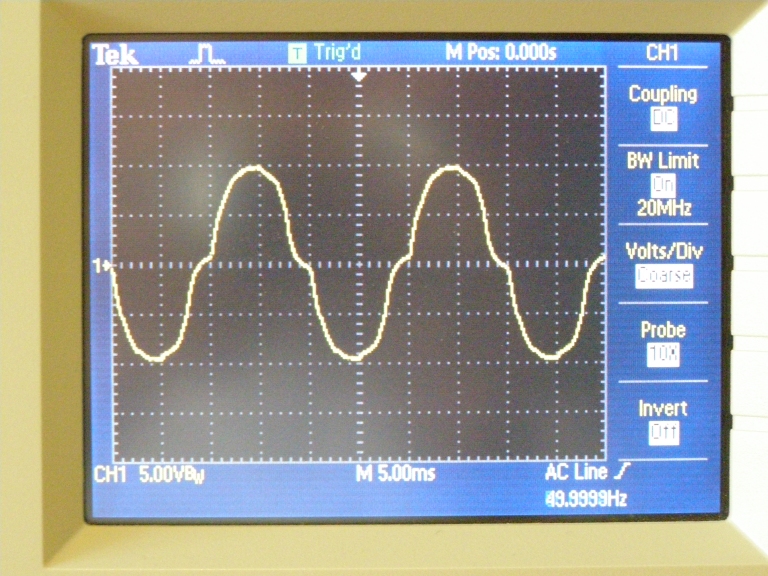 b. Probe 10x 10 MOhm |
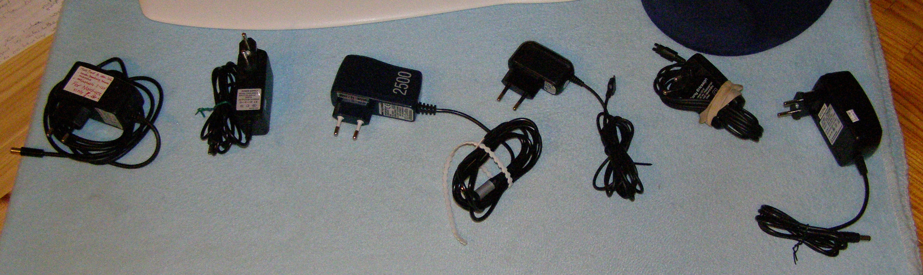
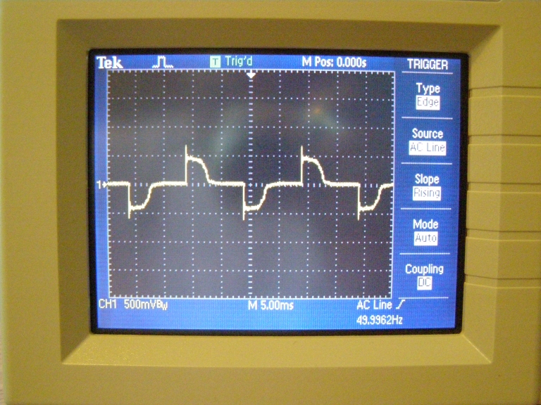
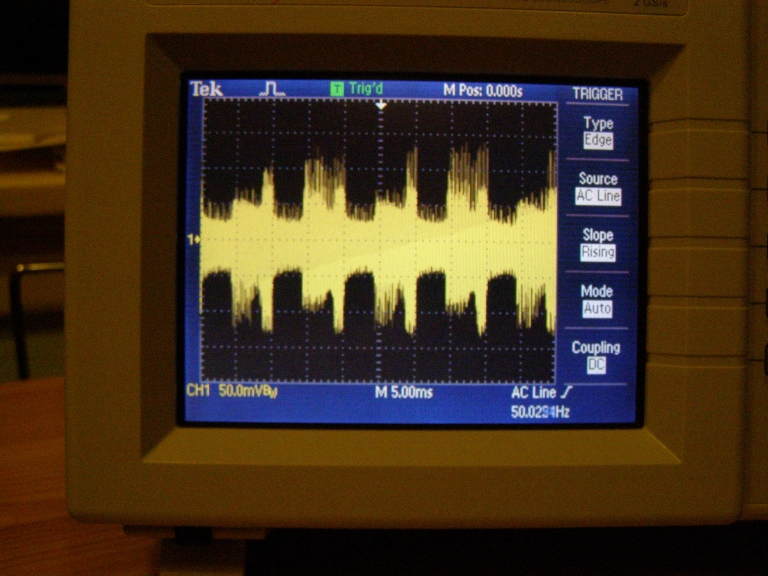
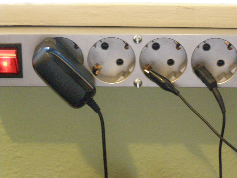 c. the best SMPS: Samsung recent cellphone charger |
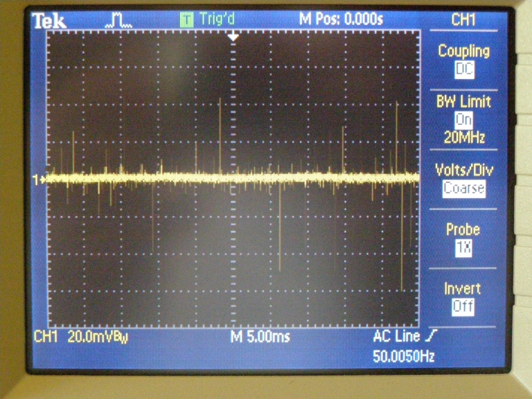 c. the best SMPS: Samsung recent cellphone charger: current image over 1k |
 c. Probe 1x 1 MOhm |
 c. Probe 10x 10 MOhm |
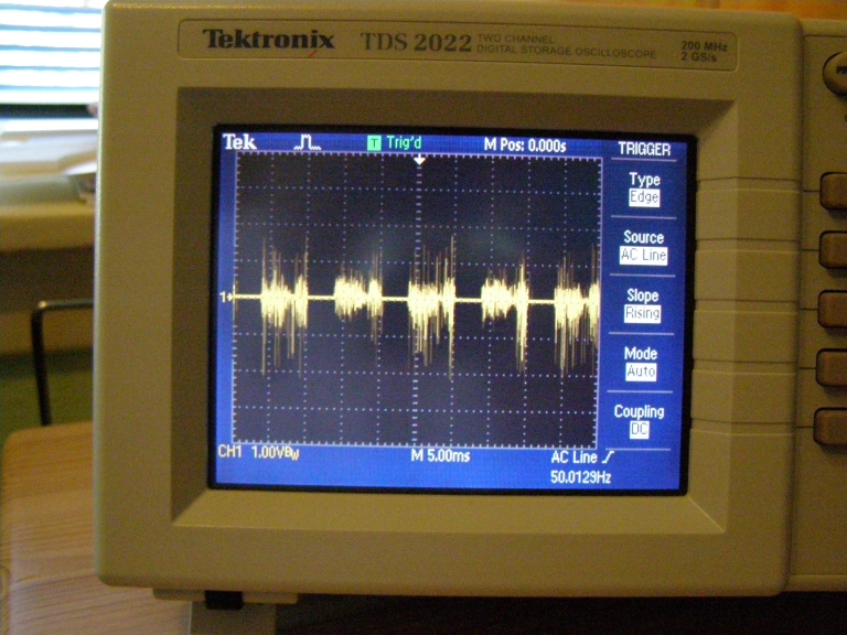
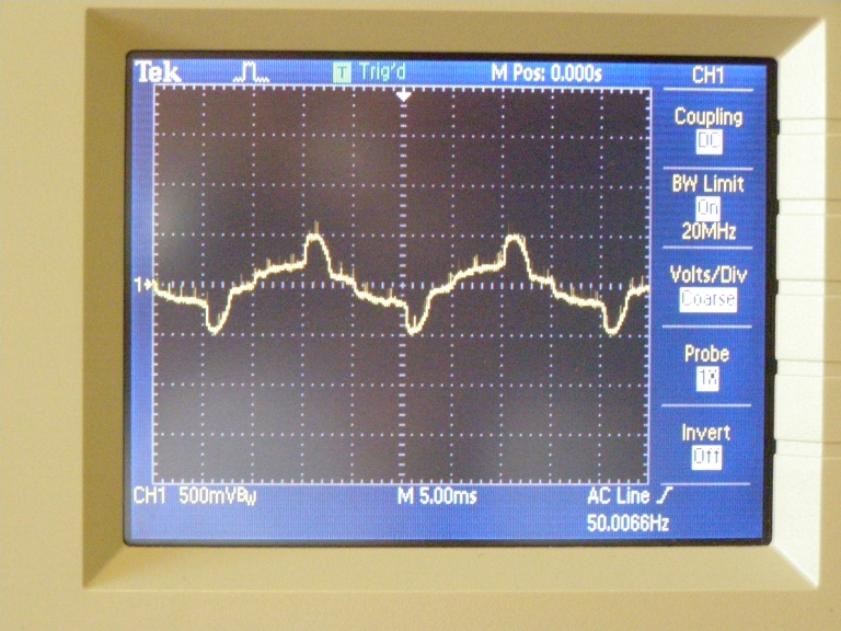
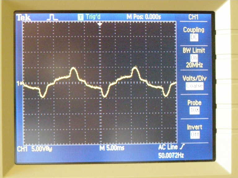
 d. the worst SMPS: Hape Univ wallwart |
 d. the worst SMPS: Hape Univ wallwart: familiar picture, isn't it ? |
 d. the worst SMPS: Hape Univ wallwart Probe 10x 10 MOhm |
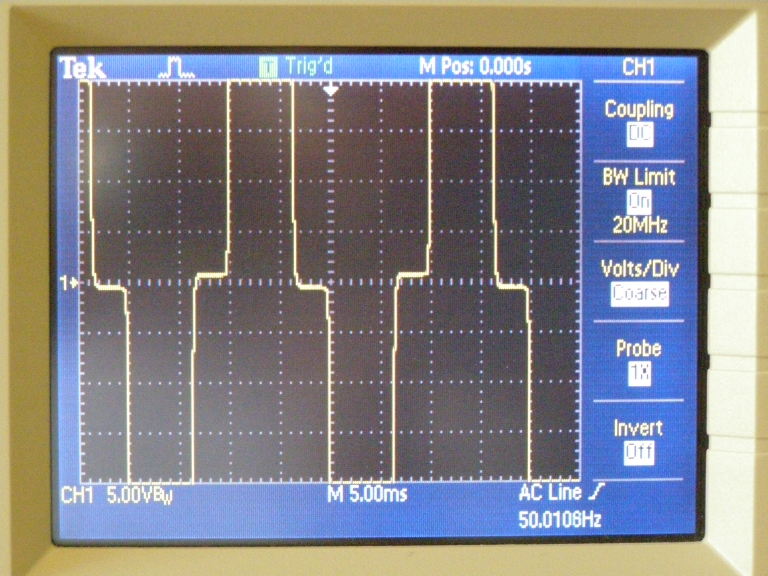 d. the worst SMPS: Hape Univ wallwart Probe 1x 1 MOhm Even with the highest sensitivity setting on the scope, the amplitude is too big to fit on the screen |