The story continues ....
The plan was to make a real decent
UV-exposure-unit. But as a wise, russian man said:
" No home project is complete
unless much tape is used " :-)
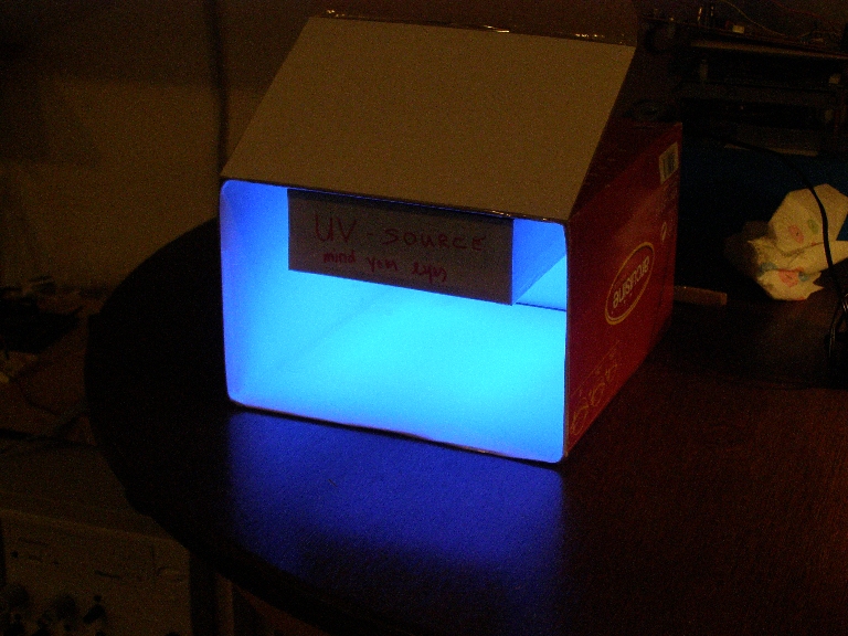
Nah ..... isn't it a beauty ?? And it works pretty good too !!
I needed to determine the optimum exposure-time for the photo-resistboards I use.
With the 24 led version, it took 40 minutes. This one has 72 !
Before going to the results, a bit about the UV-led arrangement:
 (click to enlarge)
To get a uniform intensity on the exposure area, I had to fiddle a lot with the leds:
If all are looking straight down, the center area gets about twice more light than on the edges.
By decorating the innerside of the box with white paper (even the lid !) finally I got it right
(more or less ...)
The result:
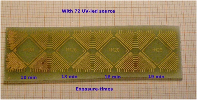
The Text M128 and the square are in "silk", so will not end up on a final board as copper.
Let's take a closer look: the 16 minutes exposure sample
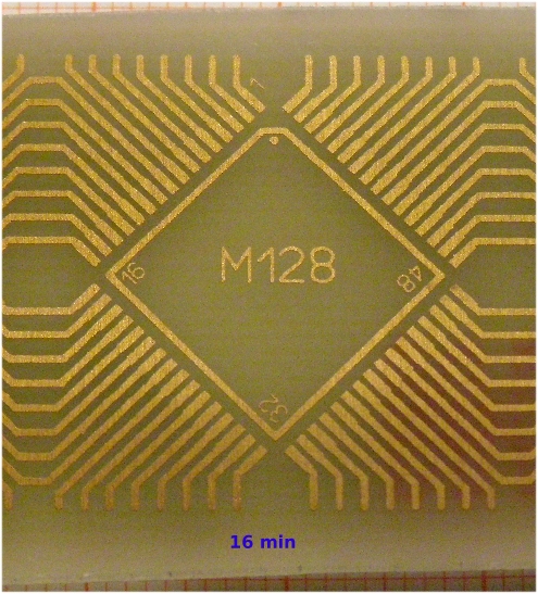
Bear in mind that this is a macro-picture: 25 * 25 mm.
The "1" in the top is less than 0.11 mm in linewidth .... or 4.3 mil
The TQFP-pads are 0.5 mm wide, the tracks 0.4 mm
The 13 minutes exposure sample looks about the same.
The 19 min. one:
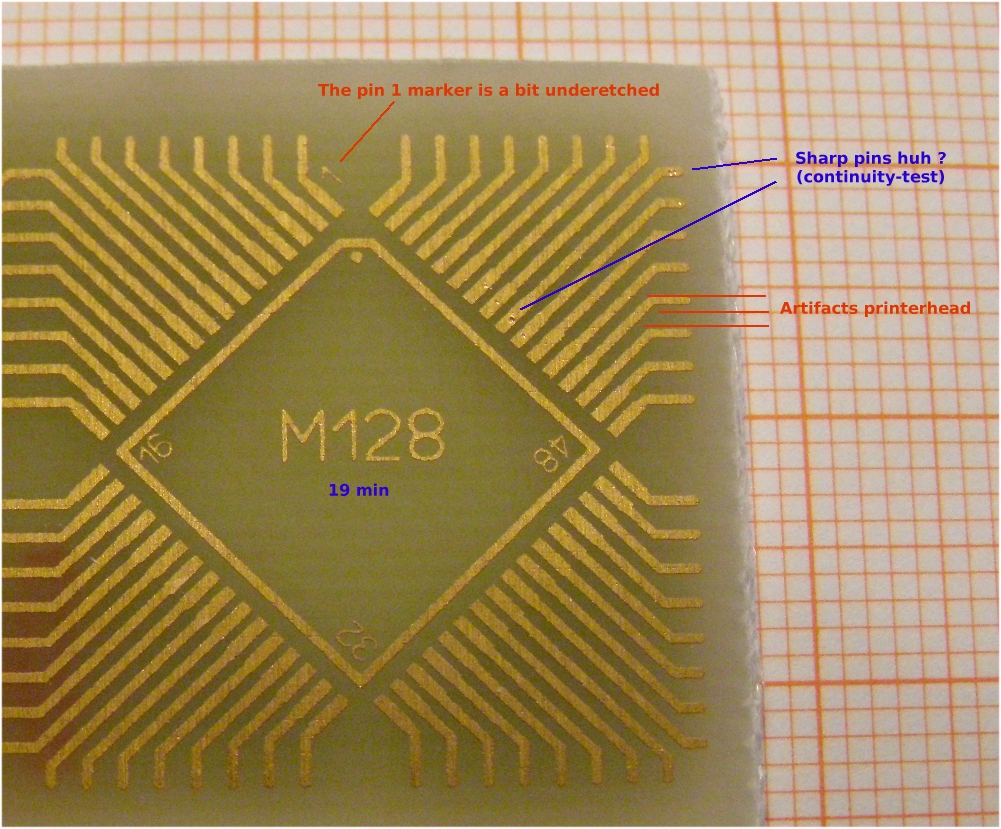
Still a very acceptable result, although a bit over-exposed.
Disadvantage of over-exposure is that the small artifacts in calque-paper and printerhead are getting more and more visible.
And can result in a cracked track.
So:
| 10 minutes: |
defenitely too short |
| 13 minutes |
Okay, but just |
| 16 minutes |
Fine :-) |
| 19 minutes |
Still okay, but slightly over-exposed |
I tested if the visible artifacts caused dis-continuity ... and they did not.
This result gives confidence for future PCB's
I started to use a new ink in the printer, so I needed to make a small adjustment:
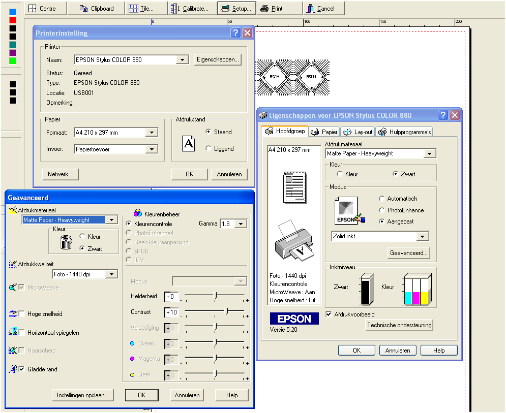
Sorry guys, texts are in Dutch, but you get the picture. I am very happy with this Epson printer. It never let me down
in quality & reliability. Despite my abuse with different inks and many cartridge-swaps.
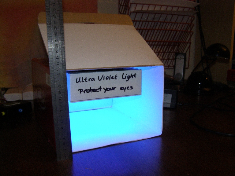
15 cm total height
 June 19, 2008
I received an email from a fellow AVRfreak who modified a low-cost aquariumpump, the Airmaster 3000
His text:
Nard,
On your Home Brewed PCB's page about searching for a vacuum pump - have you tried modifying an aquarium pump?
I bought a cheap Airmaster 3000, a dual bellows unit with no available direct suction port. An hour with a small drill bit,
hobby shop brass tubing, hot melt glue and silicone rubber tubing brought out vacuum ports.
I measured the vacuum at 41 Inches of water which converts to 3 mmHg or 100 mBar if my math is right. It does get a
bit noisier in vacuum service. The pressure output is enough to fill exercise balls too if you're not in a hurry.
Stan
And here the result:
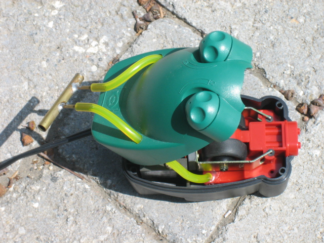
Nice mod huh ? Kwaaaak 
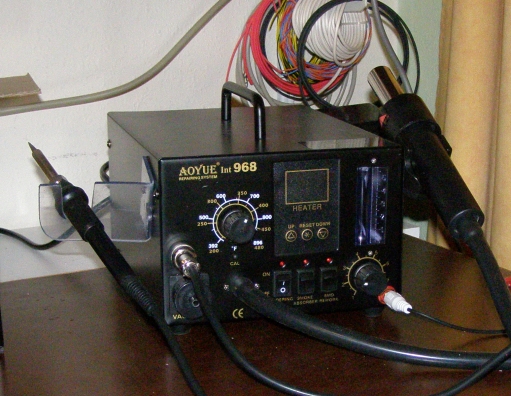
In the meantime I found a solution for the vacuumpump myself: the
SMD-workstation has a nice, quiet and adjustable pump. So now I can
expose PCB's even in the middle of the night