Voor de
nederlands sprekende bezoekers: veel van mijn collega's wonen in het
buitenland; daarom is dit deel van de site engelstalig
Home Brewed PCB's
It's been some years since I made my
own PCB's. Nowadays new tools are available, and it's much easier to
make your own PCB's now.
Eagle is a kind of standard for PCB-design, but I cannot get used to the interface.
Most of my applications are simple, so I took a simple program: Sprint Layout 5.0 from Abacom (Germany)
I will use an Epson Stylus Color 880 inkjet with overheadsheets to make the transparants
First step was gathering all the necessary stuff. More about that later.
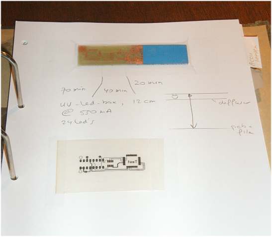
As a UV-source I have two possibilities: a skin-tanner (LOL), or ..... UV-LED's
The spec's of these 5mm UV LED
s
- Nominal current: 20 mA
- Voltage: Typ 3.60V DC
- Light power: Typ 2000mcd
- Light colour: UV 400-405nm
- Light angle: 15 degree ...... and that's why I think I need a diffusor of some kind
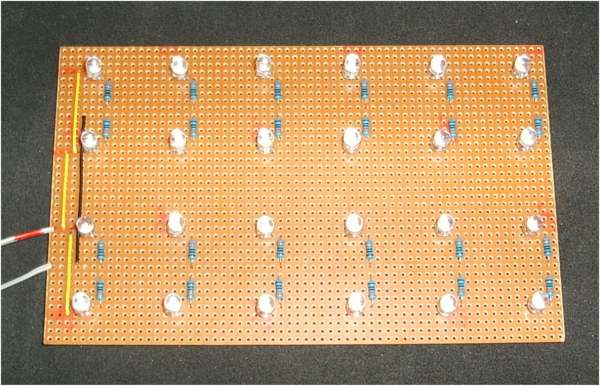
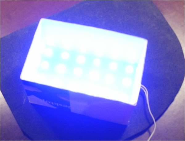
I started off with UV-LED's in a matrix of 4 * 6
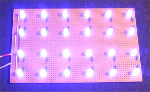
Without flashlight it looks like this: WOW !
Because of the 15 degrees opening-angle, and tolerances in wavelength, a diffuser is added:
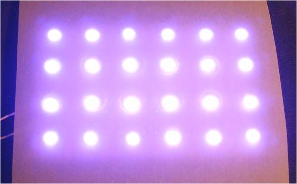
At 100 mm distance from the diffusor, projected on white paper it looks like this:
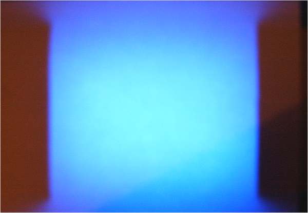
And now with markings on for Eurocard ( 100 * 160 mm ), and side-reflectors:
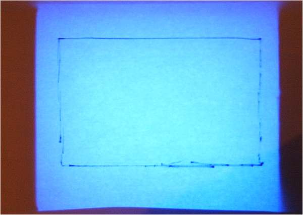
This looks promising, doesn't it ??
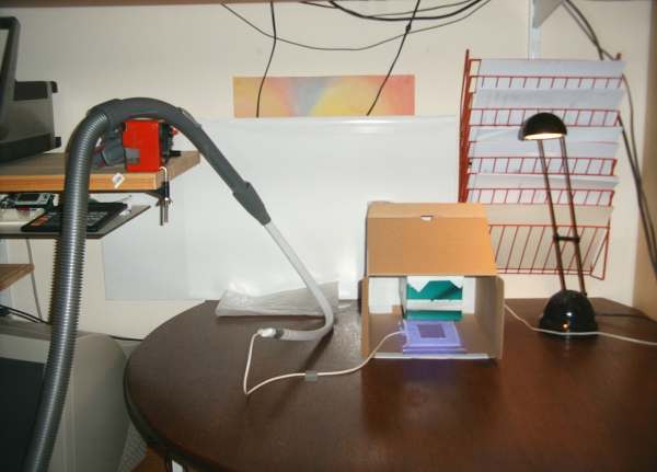
Okay, next step: giving it some kind of enclosure
I am not sure yet if the LED's will do the job (is their intensity and their wavelength OK ?)
O, and BTW: no flash used. The camera is far more sensitive for UV than my human eye (No, I am not Borged)
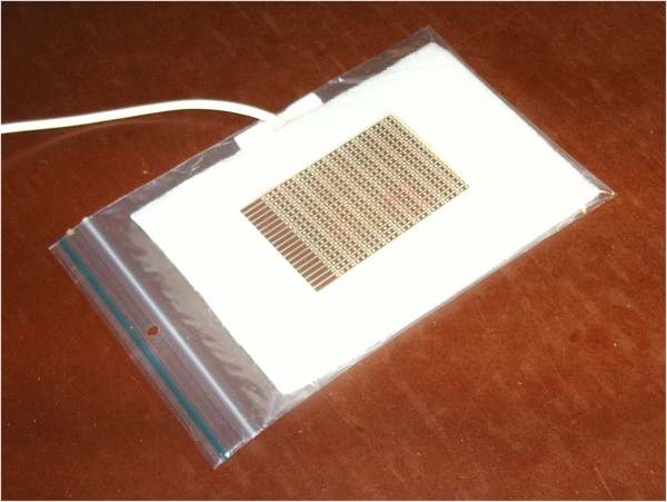
The white hose is used to get some under-pressure in the plastic bag.
Not much needed, just enough to keep the transparant firmly pressed to
the pcb.
The vero-board is just for demo-purpose of course.
Inside the plastic bag are two sheets of foam (in fact filtermaterial), the hose end between the two sheets.
This picture shows the thing in rest (no underpressure)
And here with some suction (look at the corners of the plastic bag):
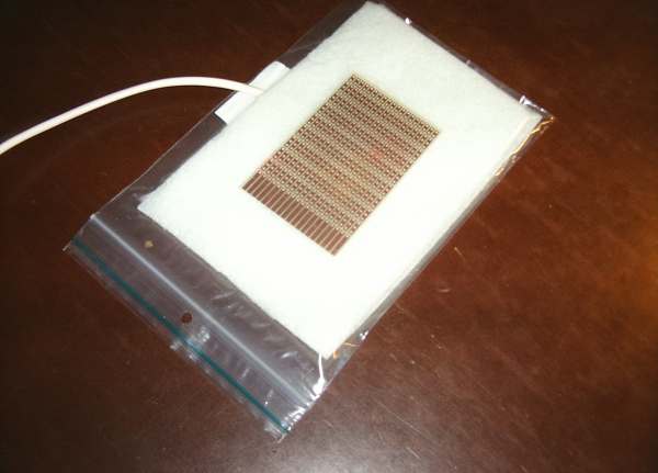
The rig is ready.
Overview:
The vacuumcleaner is set to its minimum power, and the regulator in the
handle is opened a bit ...... the vacuumcleaner needs some airflow for
cooling
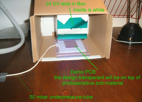
Zoomed in on the action:
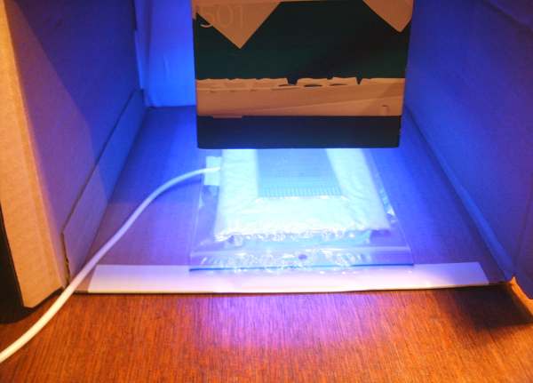
With some explaing text:
Q: why a plastic bag and not glass plate?
A: Normal glass (as used in window-panes) blocks almost ALL UltraViolet
light. Quartz would be great for this purpose, but I don't have that
lying around ;)
I will also look into Perspex (plexiglas) or Lexan, but I am afraid those are pretty well UV-blockers as well.
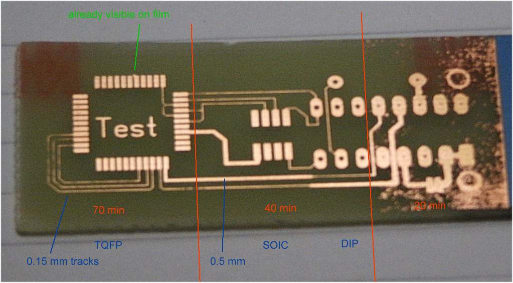
This part is ready for the test: now i need to make a pcb-test-design with PTH and SMD: SOIC, TQFP and so on.
........ time .......
And done. Now just print it out on overheadsheet, and tonight I'll have my test-pcb !
Forget it.
The ink on the film doesn't wanna dry !. In the end it will (of course) but it takes time, so to speak.
Found this site of a fellow dutchman , with some very good advice: http://www2.wau.nl/hemeltje/temporary/personal/pcb/pcb.html
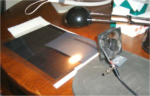
To help it a bit in the drying-process: Sun and Wind, my mother used to say.:
I also modified the UV-led-container ;) pulled it out of
the big box, added a rim to bring it upto 100 mm of the PCB-surface
Easier to handle (and store), and it gives the freedom to move over the whole filmarea. Pictures to come .....
Jan 3, 2007
Update Jan 7, 2007
O dear, I need do a lot more on this site ....
1. Lexan, Perspex, Plexiglass, Polycarbonate ..... : those work fine as well, to hold down the film on the PCB.
Didn't find the need for longer exposure.
2. I am NOT using genuine Ink-cartridges. Frankly, .... I never did. Even the first ones were non-branded. ;)
Until this film-thingie, I was quite pleased with
that NB-ink. In fact, I still am: the printer-head is still feeling fine
after many years of service, and the cost-savings are huge is: 6 times cheaper !
I have a set of new cartridges waiting, with a
different (more agressive) ink. and a re-fill-set with that same ink.
I will give the film a retry at the time the curent ones are done.
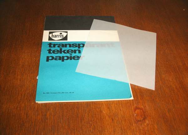
Okay then, overheadsheet transparants with this type of ink is no succes: but with calque-paper it IS !
I keep all my findings in a reference-manual .... memory does not serve me as good as it used to do.
Vintage huh ?
This material:
It's very difficult (as you can see) to get a decent-in-focus picture at that short distance: despite the macro-setting
Ok, a better one:
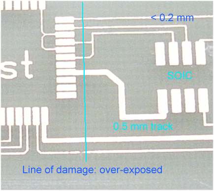
Even the tracks with less than 0.2 mm width came out fine
O yeah, I promised a picture of a Lexan-exposure .... Very nice color !!
The box is made of ...... Logitech keyboard packaging ! And with tape ..... of course !!
That's a MUST with this type of project (according to svo)
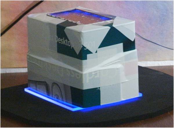
Now I know this home-process works fine, I will make a better enclosure .... some day ;)
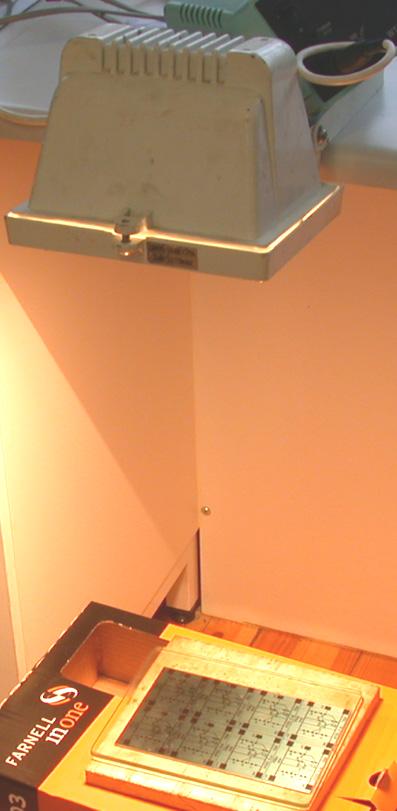
Heguli uses these 300 or 500 Watt lights: I wish I'd known that in an earlier phase of this exploration tour
Note that his floor looks like my desk ! Further down you can see for yourself .... @ the NTC
By the way: This is the thread where the PCB-making is discussed:
http://www.avrfreaks.net/index.php?name=PNphpBB2&file=index&minmax=1
With thanks to all contributing fellow-members ! Cheers !
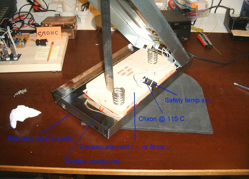
What is left ? Hmmm, aha, the modification of a standard household-dish-warming plate:
Last year, in 2006, I thought it would be a good idea to keep the chemicals warm during the process.
Knowing what I know now, I think I could have done without this attribute.
It's a 1100 Watt plate, stainless
steel top, auto-temp @ 115 degr C; when heated up it can keep up quite
a while without connection to the mains.
115 degr C is a bit too much .... so
some temp.control is required. Measuring is the first step ...... for
control there are AVR's ! The use of a PLC would be outrageously
........ HAHAHAAAA
I opened up the unit (brandnew .....), and built in the mod:
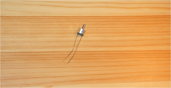
Arghhhh, terrible picture-quality ..... JPEG compression is on ... sorry for that
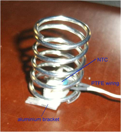
A better picture of the NTC ..... on my desk (i.e. heguli's floor ;)
After 2 hours:
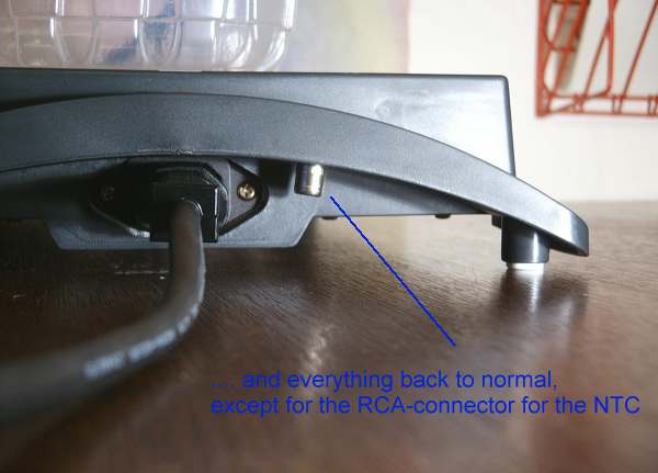
The big challenge was of course to keep the unit suitable for normal-people's use,
and yet have the added functionality that I need.
And more: to keep it safe !
I used teflon-insulated wire, in a sleeve of heat-resistant fibre. Did a clean job there, if I may say so
And for Tom and Carl: even when doing things like this, I cannot manage
to get a messy place. Terrible. Must be a genetic defect. I will never be able to post in the My Messy Work Area. :(
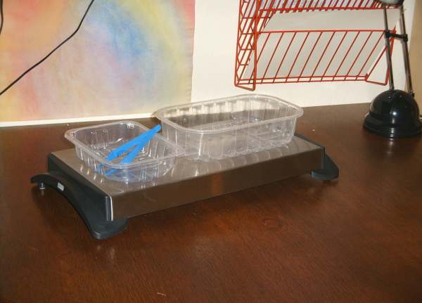
The bath-tubs for the PCB's are disposables from super-market groceries: meat and carats, if you wish to know ;)
I got some nice , more profi ones, but these disposables are great !
Nard
March 2007
40 minutes exposure-time is a bit long ...... considering the vacuumcleaner running all that time.
The new LED's have come in, so time for a rebuild:
Note the difference in color between the leds from original build (marked yellow) and the new ones (marked red)
A bit unlucky .... three leds were defective ; trying now to get some from fellow-buyers in the Netherlands.
Each string of 7 leds in series are powered by a LM317L, set-up as constant current source.
The supply is a surplus from a Lexmark-printer: it delivers 35 Volt @ max 1 Amp DC
By taking this approach, the disspation is distributed over 10 LM's, and comes down to max 200 mW per LM.
I ran out of LM's as well, but these I can get in pretty quick ...... they're on order now.
With this set-up I think the exposuretime can be reduced to 10 minutes.
For the necessary under-pressure, I consider the use of a loudspeaker. But that's still in concept ......
April 5, 2007
I built a test-rig for the loudspeaker-pump. I could have saved myself a day if I had done the math on forehand.
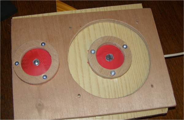
The valves consist of neoprene membrane, that's resting on a washer.
The outer-rim of the neoprene is held down with a wooden ring.
The loudspeaker will be mounted on the right side .... note the 4 screw-holes.
Feeding the speaker with a low frequency sine-wave, a cone-out-move
will increase the pressure , the valve under the speaker will close
(neoprene gets pressed onto the washer, and the overpressure will exit
via the membrane on the left. As you might have understood: there are
channels in the wooden frame. With a cone-in, the left valve will
close and the right one will open and suck air in via the white hose.
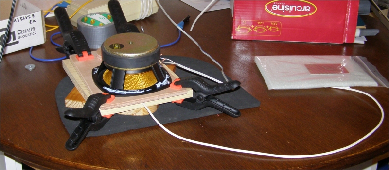
All this worked fine ...... BUT: for 10 mbar underpressure and with a
cone-surface of 100 sq. cm, the force on the cone is 1 kg ! And
that's quite something, even for a powerfull driver like the one I used.
I also tried this one: from a defective hairdryer:
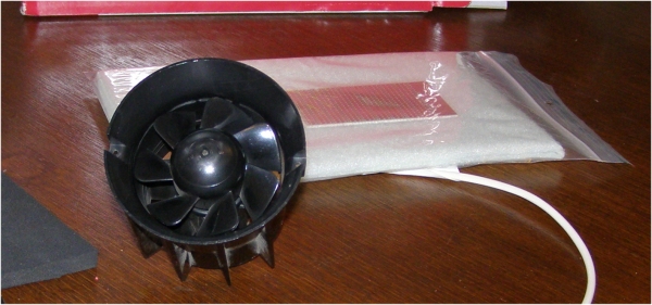
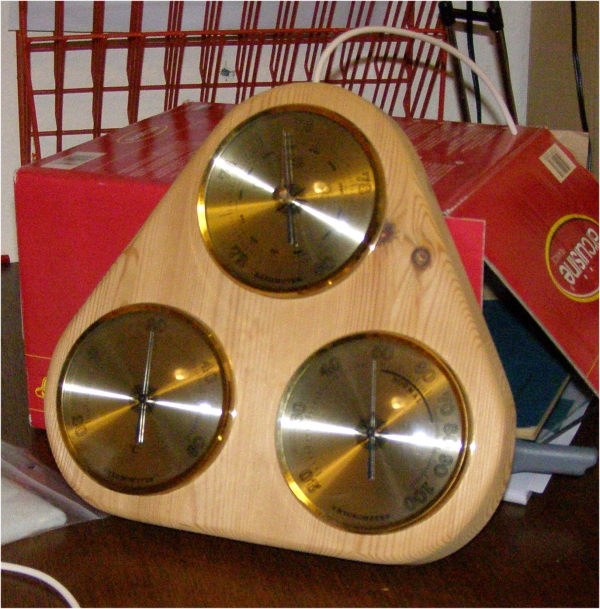
No deal. Look at the barometer (that I prepared for this task :-) )
So: either use the vacuum-cleaner, or some other pump. Both are noisy,
so no way to expose a PCB during the night (I am a night-owl)
Will be back when a proper housing for the UV is ready. And who knows ... the pump