
 March 25, 2009 : The Eagle layout package has been removed: after the third flaw it was: enough is enough :-(
The good news: I created a new one :-)
The current schematic / layout revisionlevel is rev 2 Click HERE to move to the new stuff.
: February
10, 2009 : Added Tips
to get the PPPPD working on WindowsXP <updated Feb 14 >
: April
11, 2008 : ECN 2008/5 The filter-impedance of the
filters
in the ISP-lines is reduced. This ensures proper programming,
even
when a circuit on the target-board uses these signals too.
: March
18, 2008 : ECN 2008/1 The value of R8 has been
reduced to 2k2. Reason: with a low-gain BC547,
the base-current was not sufficient to bring the transistor in
saturation. With 2k2 as base-resistor this problem will
no longer occur. Thanks to Niels (Allround)
: February
5, 2008 : Kanda released a new version of AVRISP software, and ......
released it for free download. That is very good news for those who
build/built the PPPPD: a neat plugin for AVR-Studio. Check it out and
download at http://www.kanda.com/avr-isp-software.html
Update January 2008: added pictures of my new PPPPD < no no
no no typo ;-) > It stands for Protected
Parallel Port Programming Dongle
The universal STK200/300 programmer revisited
Legal stuff:
I reserve the right to make changes without further notice to any
products herein. I make no warranty, representation or guarantee
regarding the suitability of designs or products, for any particular
purpose, nor do I assume any liability arising out of the application
or use of any product or circuit, and specifically disclaim any and all
liability, including without limitation special, consequential or
incidental damages.
In simple terms: use the information at your own risk !
On AVRfreaks.net you can find the full discussion: http://www.avrfreaks.net/index.php?name=PNphpBB2&file=viewtopic&t=36591
My username there is Plons.
To prevent that newbies get lost in such a huge thread, I decided to
publish it on my website. And that is where you are now :-)
An edited version of
this article has been published in the Dutch version of Elektor.
In Elektor's
summer-edition of
July/August 2007, a programmer for
Atmel's AVR 8-bit microcontrollers was published. This design can be
found all over the Internet, on several websites, in several forms.
It's a low-cost and simple programmer to build, is comfortable to use
in combination with Bascom AVR, PonyProg or AVRdude. And since
February 2008, Kanda released a new version of AVRISP
software,
and ...... released it for
free download. That is very good news for those who
build/built the PPPPD: a neat plugin for AVR-Studio : http://www.kanda.com/avr-isp-software.html
This article is about how to make it safe for
the PC, and reliable
for the user.
The original design has two major design-flaws, which result in either
- frustration for the user: messages like "does not recognize chip",
ID="some rubbish", or
- a damaged printerport of the PC
Good suggestions are:
- Increase the programming-delay
- In BIOS: set printerport to EPP or ECP
- Use a shielded printercable
The story:
When I purchased the STK200 from Kanda (UK), the board came with a
parallel port programming dongle and it worked fine. For several
months. Until the parallel port on the motherboard of my PC broke down.
Luckily I could fall back on a PCI-card which gave me a second parallel
port. But I was worried ..., and not amused ... but hey! .. sometimes
things just break down for no apparent reason.
A few weeks later, I needed a second programmer for a project with two
Atmel AVR's. So I built a second one based on the same design as
published in this magazine.
To suit my need for a 7 pole single in line type of connector on the
target-board, I implemented that right away. Checked my work with a
continuity-tester, and it was okay. No smoke, but IT DID NOT WORK !
Why? Did I make a mistake? No, I did not ...
Hmmm.
In order to program that second targetboard, I made an adapter-cable
for the original STK200-programming dongle. With this new cable it DID
NOT WORK EITHER !! Can a connector make the difference? Yes, ....
apparently it can. Weird huh ?
A search on the internet revealed that I was not the only one
struggling with these issues. But suggestions for a solution did not do
the trick for me. I *do* use a shielded cable, the BIOS-settings *are*
OK, I *did* increase the programming-delay, etc
This needed to be sorted out. I can't stand erratic behaviour.
Basically, it's a good design. A 74HC244 as a buffer between the
parallel port and the targetboard. When programming is done, the buffer
is disabled, which isolates the two. Good thinking of the designer!
Q. Now, what makes this dongle unreliable?
A. LONG LINES, folks! The ribboncable between dongle and targetboard is
a transmissionline. Think of Fourier, La Place, that stuff. A huge
thanks to my teachers!
The combination of a high slewrate (short rise- and fall-times) on the
signals and the (relative) long lines for these frequency-domains
(using Fourier and La Place), that is what's making these dongles
unreliable.
I hooked up an oscilloscope to the SCK-line on the targetboard and
there it was: RINGING, i.e. oscillations right after a transition of
the SCK-line.
Q. What happens during programming in the original design?
A. The AVR on the targetboard looses synchronization with the
programmer: it sees more than one SCK-clock due to the ringing. So it
looses track !
To solve this, we need to get rid of the high-frequency-components,
generated by the edges. The trick: a small RC-filter with a Tau of 0.1
us, made up with a resistor of 220 ohm and a 470 pF capacitor. That's
all it takes: one small filter in the SCK-line. I built it into the
STK200-dongle and ran some tests: problem solved. No longer dependant
of connector/cable. Built it into the second programming-dongle: works.
Hooked them up to another PC: works.
One down, one to go ...
Next problem:
Q. Was the dongle responsible for the defective printerport ?
A. No, I plead innocent. I was my own fault: Parallel ports are not
hot-pluggable. And I should have known that. But it was indeed the
dongle that killed it. Due to plugging in and out? Or was it due to
something else. Time to investigate. But first some explanation.
Imagine: the dongle is connected between targetboard and PC. Suppose
both are powered down. When the targetboard is switched on, and the PC
is not, the dongle will force current into the printerport's /Ack-line.
Q. Can that do any harm?
A. Yes!
To understand this, some historical facts about the printerport.
In the original IBM-design, it was made up with a 74LS374 and a
74LS244. To blow that port, you really needed to use brute-force. Hook
it up to 24 VDC f.i. ;-) No kidding, it was a very rugged design.
Nowadays, the functionality of a printerport (if there is one) is
realized in an ASIC, which has far more functions. That ASIC is not as
rugged as the original IBM-design. The 74HC244 in our dongle can supply
25 mA (guaranteed, so probably more!) on an output-pin, and that was
way too much for the ASIC in my motherboard. The good news is that the
rest of the board survived.
The /Ack-line requires special treatment as it has to cope with the
several implementations of the ASIC parallel port design. The value of
the pull-up on the /Ack-line f.i., can vary from 1k8 to 10 k. Using
transistor Q1 in the configuration as shown in the schematic, the
/Ack-line can be pulled low by the 74HC244 pin 9, but no current from
the 74HC244 can flow into the /Ack-line. When the 74HC244 sets the line
high, the transistor turns of, and the /Ack-line goes high by the
internal pull-up, with a little assistance from R7. So even with a
powered target-board and a PC that's turned off, we have a safe
situation.
All other lines are inputs on the 74HC244 or interconnects, so a
current-limiting resistor is sufficient for those.
The second problem is solved as well.
Some more FAQ's:
Q. Is it necessary to add the filter to MISO and MOSI as well?
A. No. The ringing on these lines (and there is !!) will have ended
before SCK clocks the data in- or out. But since we're at it, we add
filter to these lines as well.
Q. Is this the ultimate solution?
A. Depends how you look at it. Adding a filter (an analog circuit) to a
digital clock-line should be avoided. But in this case it's a proper
*and* simple solution, no matter what cable you use (within reason). It
is no speed-limiter for the programming: all software mentioned in this
article uses the bit-banging method, and that's much slower than the 2
MHz ISP-speed-limit caused by this filter. Another good thing is that
it is not built-in to cover-up for glitches due to a poor design:
because those tricks are a designer's nightmare.
Q. Could this ringing be an issue with other programmers as well?
A. Yes, I think it does. If there are high slewrates involved, and
(relatively) long lines, this is an issue.
As an example of proper design, let's have a look at the serial
programmer (SI-PROG) from PonyProg: it uses the RS232 serial port.
Bit-banged as well. But here the problem will *not* occur as in the
original RS232-specification provisions were made for
slewrate-limiting. Clever guys at that time, huh?
Some additional suggestions and/or recommendations:
1 Even with this protected dongle it's not recommended to plug-in or
unplug when either PC or targetAVR are powered-on. In case you REALLY
need to do a plug-in, first touch the shell of the 25p connector to the
chassis of the PC. Static built-up will be equalized.
2 For PPPD to work properly, Vcc of your targetAVR should be 5V. It
will probably work too with lower voltages, but this design does not
provide level-shifting. So if it works, treat that as a bonus.
3 If you use the STK200-board as target, 3.3V for the target-AVR is OK
as the STK200 has additional circuitry that provides the level-shifting.
4 If you need to disconnect the programmer from your targetAVR, first
switch the target off.
5 Leave the PPPD connected to the PC; there is no need to plug/unplug
it each time.
6 If you're using a ParallelPort extension cable, make sure it's a
shielded one, not longer than 1.8 mtr
7 Check your PC-BIOS for ParallelPort setting: choose EPP or ECP, *not*
SPP
8 Be aware that in the original design of STK200 dongle (and possibly
more), the ribbon-cable between PPPD and the target-board is NOT 1:1.
The connector on the dongle is rotated 180 degrees, which means that
pin no.1 on one side is NOT pin no.1 on the other side. So check the
connections BEFORE applying power.
The costs:
Implementing all these measures takes just a bunch resistors, three
capacitors, and one general purpose transistor. A very low price
compared to the damage it can do to your PC. And: it will also save you
many hours of trying to sort out what is wrong with the programmer that
worked fine yesterday, and doesn't work today. Or works on one board,
but doesn't on another ...
Sometimes solutions can be so simple ...... for such complex problems.
Cheers !
Plons
Links:
http://www.lancos.com/prog.html
PonyProg website
http://savannah.nongnu.org/projects/avrdude/
to download the latest version of AVRdude
http://www.atmel.com/dyn/resources/prod_documents/DOC0943.PDF
Atmel AVR910 Application Note; here you can also download AVRStudio,
the free development software from Atmel.
http://www.mcselec.com/
for
BascomAVR. A free, yet fully functional demo version can be downloaded.
Compared with the full version, it's only limited in compiled program
size: 2 kb maximum.
http://www.expresspcb.com/ for the
program I used for the schematic.
http://www.kanda.com/avr-isp-software.html
for the AVRISP-program that can be used as a plug-in in AVR-Studio.
Credits:
I tried to find out who designed this dongle in it's original form.
The
schematics can be found all over the Internet, in several places, in
several forms.
It is not clear what's the genuine one. I wish to
express my gratitude to the original designer.
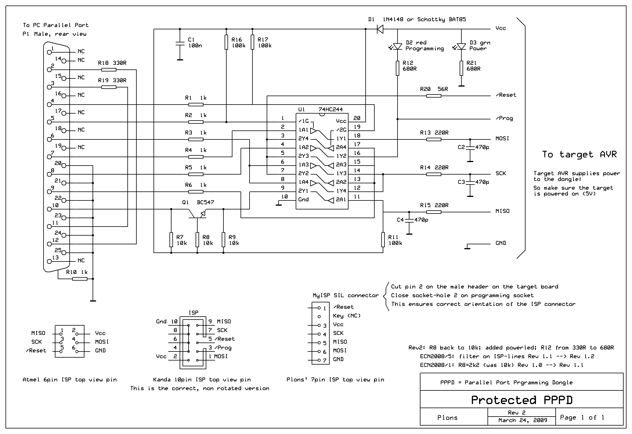
The Protected Parallel Port Programming Dongle in all its glory:
The schematic is drawn with ExpressSch. You can find the program on my Tools-page.
The
.sch-file of the PPPPD can be found here
Next
the .png-file. Right mouse-click, Save As etc. It will look much better
then as well :-)
March 25, 2009 The layout
I deleted the Eagle version from this webpage as it turned out there were several errors in it.
But no need to be sad: there is a new layout available. Fresh, double checked but has never been built yet.
The layout was made with SprintLayout5.0. The Viewer program of SprintLayout5.0 can be downloaded from my Tools-page
Instructions can be found there. The layout-file of the PPPPD can be found here
An impression:
The value of the components can be found in the silkscreening (red),
and the following system is used: <digit> <digit>
<number of 0's>
331 stands for 330 Ohm or 330 pF , 104 stands for 100 kOhm or 100 nF ( 100 kilo pico Farad )
560 stands for ..... 56 Ohm, NOT 560 Ohm.
The layout is of the Single Sided type: (just) one wire-bridge , the 0R resistor.
Tracks and pads are pretty fat to make the design forgiving for
over-exposure, under-etching and easy-to-be-frilled. I've thought of
everything ;-)
As a bonus a green LED is added, LED-current is reduced, but even now there is plenty of light coming out of them.
Do you wish to contact me ? Compose the email address by taking the 5
characters of this design, yes, the 5 that make you stutter, add the
curl that can be found in any email address, followed by the domainname
you that is in your URL-bar at THIS very moment. A bit clumsy, but
necessary because of spam.
For those who use the Parallel
Port on a PCI-card: the following pictures may be helpfull.
Sorry, it's in Dutch, but you get the picture
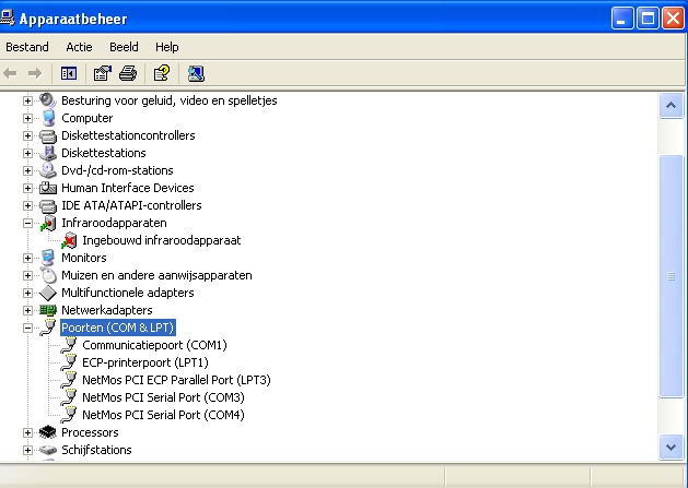
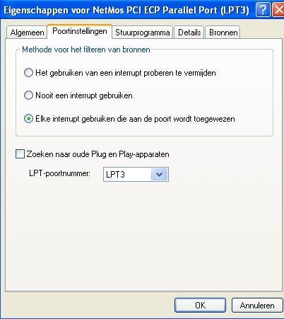
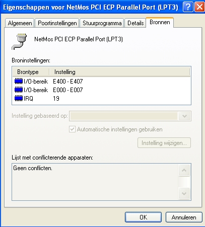
Note: a
USB-to-printerport adapter CANNOT be used with this dongle. You need a
PCI expansion board.
Tips to
make the PPPPD working on
a WindowsXP system
When you have checked your PPPPD-hardware, but it still doesn't work,
here some more things to check:
- Search for giveio.sys on your PC; most likely to be found on
C:/Windows/System32 ; this file is needed to get access to the IO-port.
Can also be found in WinAVR-package. To get access
to the port you need to run install_giveio.bat
from winavr\bin (in windows); this script also loads the driver.
The
batchfile and giveio.sys in this
zipped package With thanks to Fabiar !
- Still no luck ? Then:
Install a printer, like HP Laserjet 4500. That's a parallel port
printer. No, you don't need to actually have that printer, we just want
the driver installed. WinXP does that without the need for the CD. Just
run the "Add a Printer" -wizard; you get a huge list of brands and
types. Select that HP one, Windows does its work, and of course you
don't select it as your default printer, nor print a test-page (indeed,
I have had questions about that :-S )
Still no "Hoeraaaaaayyyy !! " ???
- Unpack the RegistryFix,
read the info, and implement the register-change (it can be undone, but
make a "Restore point", just to be safe ... )
The attachment comes from Kanda.com. It can be found on their website,
but it's not simple to find.
Background info: from SP2 and on, WinXP checks the Parallel Port every
minute or so to find out if the user attached a printer. That
interferes with our use of the PP. The registry-patch ensures that the
PP is still checked, but only during a Power-up sequence.
- If you use PonyProg, and still no success ? Try avrdude. Can be found
in WinAVR-package. Make sure to read the documentation..
- Using Bascom ? Check the Help. And run Setupio.exe that you can find
in the main Bascom-folder.
Still no working PPPPD ? Be kind to yourself, and stop spending
time on it. Consider to buy an AVRISP. http://www.kanda.com/avr-programmer-support.php3
for example
Or this one: http://www.mcselec.com/index.php?page=shop.product_details&flypage=shop.flypage&product_id=104&category_id=3&option=com_phpshop&Itemid=1
No money to buy it ? Then build the Serial version of a programmer. You
can find it on the Lancos-site. It will be slow, but will work ( if you
did a proper build of it of course )
Do you still want to debug this PPPPD any further ?
Download these two: ParPortViewer
readme and ParallelPortViewer
Now you can start debugging: first make sure that the Parallel Port of
the PC is still OK Use the program to set/clear bits, and
check the pins with multimeter
(f.i.)